miércoles, 28 de marzo de 2012

Knob Class for Processing 2.0

I just finished a knob class (library) for processing. The idea is simple... The need of using a knob on my sketches using a simple class and interact with my microcontrollers. The goal is to have a class that can be used in a very simple way.

The video shows how to use a knob class and a designer tool for getting the final geometry of a knob.

The knob class is useful to create sophisticated GUIs using Processing, a graphical java based programming environment.


Using in conjunction with the button class (previous article) we can create GUIs to interact with, showing values from variables, that we can read from microcontrollers like arduino. We'll show in the next article how to do it.

Also we can use a knob for change values to modify other widgets or for dim a led or change the brightness of a LCD connected to a arduino... uses are circumscribed to the imagination and needs.

Meanwhile, it is worth to understand the basics of the library (class).

The following example uses the knob class to change the background color of the window created in processing, using 3 knobs each one handling a component of a RGB tuple.


(1) ADknob rcolor, gcolor, bcolor;
int r,g,b;
(2) void activateMouseWheel()
{
 addMouseWheelListener(new java.awt.event.MouseWheelListener() 
 { 
   public void mouseWheelMoved(java.awt.event.MouseWheelEvent evt) 
   { 
     mouseWheel(evt.getWheelRotation());
   }
 });
}
(3) void setup()
{
   size(500,200);
   smooth();
   rcolor = new ADknob("R",100,100,45,255,0.0,1.0,4.0,20.0,34.0,19.0,34.0,15,7,53.0,20,19,10,-6,14,5,9,14,7,23,false,11,0);
   rcolor.setKnobPosition(234);
   rcolor.setColors(#D30606,0,-1,0,0,0,0,-11574371,-327681);
   gcolor = new ADknob("G",250,100,45,255,0.0,1.0,4.0,20.0,34.0,19.0,34.0,15,7,53.0,20,19,10,-6,14,5,9,14,7,23,false,11,0);
   gcolor.setKnobPosition(202);
   gcolor.setColors(#0FA705,0,-1,0,0,0,0,-11574371,-327681);
   bcolor = new ADknob("B",400,100,45,255,0.0,1.0,4.0,20.0,34.0,19.0,34.0,15,7,53.0,20,19,10,-6,14,5,9,14,7,23,false,11,0);
   bcolor.setKnobPosition(111);
   bcolor.setColors(#050EA7,0,-1,0,0,0,0,-11574371,-327681);
   activateMouseWheel();
}
(4) void draw()
{
  background(color(r,g,b));
  r=(int )rcolor.update();
  g=(int )gcolor.update();
  b=(int )bcolor.update();
}
(5) void mouseDragged()
{
  rcolor.change();
  gcolor.change();
  bcolor.change();
}
(6) void mouseWheel(int delta)
{  
  rcolor.changeKnobPositionWithWheel(delta);
  gcolor.changeKnobPositionWithWheel(delta);
  bcolor.changeKnobPositionWithWheel(delta);
}

(1) Object Creation
  1.1 We start creating one object for red, green and blue component of the RGB tuple
  1.2 And three integer variables for storing the knob values.

(2) The function activateMouseWheel
  2.1 Enable us to activate a listener for the mouse's wheel.

(3) Inside the setup function
  3.1 We define the windows with size() function
  3.2 We instantiate each knob with the parameters obtained from the knob tool
  3.3 We also set the value of the knob. This is necessary for setting an initial (r,g,b) background
  3.4 Finally we call for the activation of the mouse wheel

(4) Inside the draw() function
  4.1 We change the background using the variables r,g,b
  4.2 These values are obtained from the knob.update() function, which is in charge of return
        the value and draw the knob itself

(5) The mouseDragged() function
  5.1 Enable us to call the change() method of each knob while the mouse is dragged over the knob
  5.2 This function is also responsible of redrawing the knob on the screen

(6) the function mouseWheel()
  6.1 It is called by the listener of the mouse using the increment or decrement of the wheel mouse
  6.2 Inside we call the changeKnobPositionWithWheel() method for updating the knob

The structure of the code is very simple as I will describe next:

(1) Create the knob Object
(2) Instantiate the knob with the parameters obtained from the tool inside the setup() function
(3) Get the knob value and use it inside draw() function
(4) Create a mouseDragged() function to call the change of the knob if we drag the mouse over
(5) Create a mouseWheel() function to call changeKnobPositionWithWheel() when we use the wheel

Interaction:

The knob can be used dragging the mouse over it or using the mouse wheel or the keyboard.

(1) Mouse Wheel
  1.1 The wheel is used to increment or decrement in one step at a time
  1.2 Shift+wheel increments or decrements the knob at totalSteps/10 ratio
  1.3 Ctrl+wheel increments or decrements the knob at totalSteps/4 ratio

(2) Keyboard
  2.1 LEFT || DOWN decrements the knob at totalSteps/10 ratio
  2.2 RIGHT || UP increments  the knob at totalSteps/10 ratio

Look at the video to see more details about the class and the tool and download the source to essays different examples.

Download: knob class
Download: button class
Download: color example
Download: Designer tool


Read More......

sábado, 17 de marzo de 2012

VIDEO: Button Class for Processing helps Arduino's Interaction

This is a very short video which demonstrates how the button class helps to interact with a microcontroller like teensy (arduino clone).


DISCLAIMER **
THIS SOFTWARE IS PROVIDED TO YOU "AS IS," AND WE MAKE NO EXPRESS OR IMPLIED WARRANTIES WHATSOEVER WITH RESPECT TO ITS FUNCTIONALITY, OPERABILITY, OR USE, INCLUDING, WITHOUT LIMITATION, ANY IMPLIED WARRANTIES OF MERCHANTABILITY, FITNESS FOR A PARTICULAR PURPOSE, OR INFRINGEMENT. WE EXPRESSLY DISCLAIM ANY LIABILITY WHATSOEVER FOR ANY DIRECT, INDIRECT, CONSEQUENTIAL, INCIDENTAL OR SPECIAL DAMAGES, INCLUDING, WITHOUT LIMITATION, LOST REVENUES, LOST PROFITS, LOSSES RESULTING FROM BUSINESS INTERRUPTION OR LOSS OF DATA, REGARDLESS OF THE FORM OF ACTION OR LEGAL THEORY UNDER WHICH THE LIABILITY MAY BE ASSERTED, EVEN IF ADVISED OF THE POSSIBILITY OR LIKELIHOOD OF SUCH DAMAGES.


Download source: ledSwicthesWithButtons.pde
Download source: buttonClass.pde

Read More......

viernes, 16 de marzo de 2012

Simple Button Class for Processing


Abstract

Continuing with our goal of communicating with arduino like micros, this time I brought you with a simple button class to use with processing. I've made a simple example of how to use it and also I have created a more elaborated example, using the buttons to turn on/off leds of my teensy.


Simple Button Class for Processing

The idea is to use it, as is, with no knowlegde about how to code a button... that' s why this class is like a library.

DISCLAIMER **
THIS SOFTWARE IS PROVIDED TO YOU "AS IS," AND WE MAKE NO EXPRESS OR IMPLIED WARRANTIES WHATSOEVER WITH RESPECT TO ITS FUNCTIONALITY, OPERABILITY, OR USE, INCLUDING, WITHOUT LIMITATION, ANY IMPLIED WARRANTIES OF MERCHANTABILITY, FITNESS FOR A PARTICULAR PURPOSE, OR INFRINGEMENT. WE EXPRESSLY DISCLAIM ANY LIABILITY WHATSOEVER FOR ANY DIRECT, INDIRECT, CONSEQUENTIAL, INCIDENTAL OR SPECIAL DAMAGES, INCLUDING, WITHOUT LIMITATION, LOST REVENUES, LOST PROFITS, LOSSES RESULTING FROM BUSINESS INTERRUPTION OR LOSS OF DATA, REGARDLESS OF THE FORM OF ACTION OR LEGAL THEORY UNDER WHICH THE LIABILITY MAY BE ASSERTED, EVEN IF ADVISED OF THE POSSIBILITY OR LIKELIHOOD OF SUCH DAMAGES.

A simple example in the following lines:


ADbutton button1;
 boolean pressed=false;
 void setup()
 {
     size(290,120);
     smooth();
     button1 = new ADbutton(80, 40, 150, 30, 7, "Press Me");
 }
 void buttonRun()
 {
     if (pressed)
       button1.label("Press Me");
     else
       button1.label("unPress Me");  
     pressed=!pressed; 
 }
 void draw()
 {
     background(#04583F);
     if (button1.update())
        buttonRun();
 }

A very simple approach to use button to run functions each time a button is pressed. This example instantiate button1,inside setup(), based on ADbutton class indicating (x,y) position on the screen, (width,height) of the button, radius of the rounded corners of the button and the label.

Then, on function draw() we run button1.update() that has to goals: the first one is to draw the button itself and the second one is to return a boolean indicating if the button was pressed.

If the button was pressed is evaluated at the if statement. If the returned value is true it runs buttonRun() function.

In the buttonRun() function we evaluate the boolean pressed variable to change the label of the button, so it behaves like a push button.

The better way I found to use the class is to create a tab on processing, copy and paste the code and then create your program in the main tab using the class.

The video shows the quick deploy of the class...


Download: buttonClass.pde
Download: arrayOfButtons.pde

Read More......

sábado, 10 de marzo de 2012

Internet of things: Sending data to Twitter using Python - part I

Abstract

Continuing with the goal of sending data using different means to connect a microcontroller to the outside world, this time we are going to describe how to interact with twitter as a way to show messages triggered by conditions defined and showing values of any kind of sources.

This article is divided in 2 parts. The first one is intended to show you how to send data from our computer to twitter. The second one is going to be dedicated to explains the procedure that have to be followed to send data produced by different sources to Twitter.

See the video:


Sending data to Twitter - part I

What we want to do is obtain data from a source (i.e. a sensor), then analyze it to trigger messages depending on specific conditions. With this goal in mind the first step is to know how the messaging system of twitter actually works.

In order to send messages  to twitter from command line it is not enough to use curl or whatever command line tool to send messages over internet. Instead, Twitter clients will need to use more secure authentication based on OAuth. OAuth is an authentication protocol that allows users to approve application to act on their behalf without sharing their password.

So this first part is going to help people to know what is the lifecycle to get ready for sending messages.

(1) Download Tweepy

To interact easily with Twitter from Python, is imperative to get in hand an API that can be used to get an abstraction, this way is easier to program what we need. It is worth to say that Tweepy is a very well documented Twitter library for Python. This is the python API that we will use to authenticate against twitter and send messages.

(2) Create the application on  https://dev.twitter.com/apps

Here you can create as much as applications as you need. This step will provide you with two authentication pieces required for the next step.


CONSUMER_KEY
CONSUMER_SECRET

It is important to remember to configure the application to Read, Write and Access direct messages located on settings tab.


(3) Authenticate against the application created in the above step.

This step engage with the authentication procedure of twitter and will provide you with another two pieces required to send the messages.


ACCESS_KEY
ACCESS_SECRET

The following script do this engage, just replace key and secret.


#!/usr/bin/python


import tweepy
CONSUMER_KEY = 'put here the consumer key'
CONSUMER_SECRET = 'put here de consumer secret'
auth = tweepy.OAuthHandler(CONSUMER_KEY, CONSUMER_SECRET)
auth_url = auth.get_authorization_url()
print 'Use this URL to get the PIN: ' + auth_url
PIN = raw_input('PIN?: ').strip()
auth.get_access_token(PIN)
print "ACCESS_KEY = '%s'" % auth.access_token.key
print "ACCESS_SECRET = '%s'" % auth.access_token.secret


Execute the script, copy and paste the url on your favorite browser and get the PIN. Introduce this PIN number and the script will print the access_key and access_secret required for the next step.

(4) Sending messages to Twitter

With the information gathered before and a script created using the Tweepy API it is very easy to send messages. The following code is depict the simple procedure of getting the message using a command line parameter and then send the message to twitter.


#!/usr/bin/python
#sendMessage2Twitter.py
import sys
import tweepy
CONSUMER_KEY = 'put here the consumer key'
CONSUMER_SECRET = 'put here the consumer secret'
ACCESS_KEY = 'put here the access key'
ACCESS_SECRET = 'put here the access secret'
auth = tweepy.OAuthHandler(CONSUMER_KEY, CONSUMER_SECRET)
auth.set_access_token(ACCESS_KEY, ACCESS_SECRET)
api = tweepy.API(auth)
api.update_status(sys.argv[1])

So, the last line get its argument from command line and update the status of our twitter, just by doing this.

./sendMessage2Twitter.py "This is a test of sending messages to twitter from command line using #teewpy and #python"

You can extend the script to gather any kind of information and send it to twitter. The next article will be dealing with getting info from a microcontroller and send it to twitter using this procedure.

VIDEO


Enjoy!


Read More......

lunes, 27 de febrero de 2012

Sending temperature data to pachube using pic based microcontroller


Abstract

In my previous article I described a way to send data to a feed created on pachube to store data that came from a temperature sensor of my laptop. The article was intended to show the procedure that has to be followed to send data to pachube's feed.

In this article I am going to show you how to obtain data from a lm35 (temperature) sensor attached to a arduino like board (pinguino), send them to pachube's feed and then visualize the data using Komposer.

Sending temperature data to pachube using pic based microcontroller

The first thing that we have to understand is the whole picture. The following image shows you how is  the relationship among the different components.


The components required are:

1x LM35 Precision Centigrade Temperature Sensor
1x Pic 2550 based Pinguino (arduino like board) or arduino board(1)
1x PC using linux (I use Ubuntu 11.10) with python installed

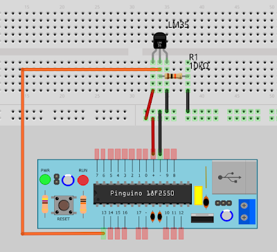
The above image shows the LM35 sensor attached to the microcontroller which is responsible for reading the analog pin where the sensor is attached, calculates an average of the values red and converts them to centigrades, then send this value through the serial port to the PC.

The PC will receive the values through the serial port where a python script is in charge for reading each value of temperature and send it to pachube's feed (previously created on pachube's web site).

A third component is related to the way we can access the data in a form of a charts such that we can easily see temperatures trends over an hour, a day or a week. This component is a simple static web page created with komposer.

Firt things first

The first thing we have to solve is reading the sensor from the microcontroller. To do this we have to have the components and attach them using a protoboard.


I have used fritzing to do this model where you can see the lm35 attached to the pin13 of our pinguino. The pin 13 is analog so it is suitable to read different voltages (0-5V). The LM35 is very simple to connect and read. It has only 3 pins (VCC, VOUT, GND). This link has a very good tutorial of how to read and convert the Vout value so the reading sent to the serial port is easily read in its final scale.

For this schematic we have used a pull-up 10K resistor due to the fact that pinguino 2550 lacks of these internally. VCC and GND comes directly from the pinguino VCC and GND.

With this all set on our protoboard it is time to load the code on the micro using the 32 bit Pinguino's IDE.


byte pinTemp=14;


void setup()
{
   pinMode(pinTemp,INPUT);
}


float temp(byte pin, int n, int milis)
{
  int i=0;
  int valorPin=0;
  //read cycle defined by n iterations waiting (millis) milliseconds
  for (i=0; i<n; i++)
  {
    valorPin= valorPin + analogRead(pin);
    delay(milis);
  }
  //return the average value coverted to celcius
  return (5.0 * (valorPin/n) * 100.0)/1024.0;  
}


void loop()
{
   CDC.printf("%d\n", (int)temp(pinTemp,100,600));
}

A little explanation of the code:

1) On the setup() block we initialize the pin as an analog input.
2) On the loop() block we print the result to the serial port using CDC and the custom temp() function.
3) On the temp() function we calculate the average of 100 values red with analogRead(), each one executed every 600 milliseconds, then return the value converted to centigrades.

With 100 reads each one executed every 600 millis we will obtain a temperature value every minute or so. This value is sent to the serial port (/dev/ttyACM0) and can be red with the following script using python.

#!/usr/bin/python

"""
tempLM35.py
"""
import os.path
from datetime import datetime
import serial
import signal
import sys
import subprocess
import eeml

pachubeURL="/v2/feeds/47024.xml"
pachubeKEY="bfr0eqPG26CdsRgwTOrgIPZV86DRGJr1q9Ept4ZjaJ8"

#Verificacion del parametro indicando el puerto serial /dev/ttyXXX
if len(sys.argv) > 1:
   if os.path.exists(sys.argv[1]):
      puerto = sys.argv[1]
   else:
      print "El puerto especificado %s no existe!" % (sys.argv[1])
      sys.exit(1)
else:
   print "uso: showSerial.py /dev/ttyXXXX"
   sys.exit()

#Apertura puerto serial
try:
   ser = serial.Serial(puerto, 9600)
except (serial.ValueError, serial.SerialException):
   print "\n::Error::\n Puerto=%s" % (puerto)
   sys.exit(2)

#Funcion para el catch del ^C
def signal_handler(signal, frame):
   print ' Saliendo...'
   ser.close()
   sys.exit(0)

signal.signal(signal.SIGINT, signal_handler)

pachube = eeml.Pachube(pachubeURL,pachubeKEY)
#while 1:
try:
   result=ser.readline()
except serial.SerialException:
   print "\n::Error::\n Puerto=%s" % (puerto)
   sys.exit(2)

result=result.replace("\n","")
pachube.update([eeml.Data(0, result, unit=eeml.Celsius())])
pachube.put()
print "("+str(datetime.now())+") --> "+result+" Celsius"

At the end of this code we use the eeml library to update and send one value to the feed 47024 referred with pachubeURL variable using our unique key for authentication (pachubeKEY).

This script have to be executed each time we decide to obtain a value from the serial port and send it to pachube's feed. Linux give us a tool called cron. Updating the crontab to execute the script every minute allows us to send the data at the same rate of the microcontroller.

* * * * * /home/ydirgan/SCRIPTS/pachube/tempLM35.py /dev/ttyACM0 >>/home/ydirgan/SCRIPTS/pachube/tempLM35.out 2>&1

The last line of the python script prints out the following formatted line (ie):

(2012-02-27 12:18:19.740213) --> 28 Celsius
(2012-02-27 12:19:10.317034) --> 29 Celsius
(2012-02-27 12:20:51.447645) --> 28 Celsius
(2012-02-27 12:21:41.929904) --> 28 Celsius

As you can notice on the cron entry above, the script is executed redirecting the referred output to tempLM35.out which will contain the historical values red from the sensor. This file can be used to create a chart on (i.e.) a libreoffice spreadsheet utility. Instead, we use pachube to store that data and let it to create the charts.

Finally using the same technique from our last article (using komposer) we can show the charts in one page and using labels to identify the charts and to make easier the interpretation.

Using an auto-load plugin on the browser you can keep up to date this page to see what is going on with the temperature of the room.

follow us on twitterG+ or Facebook
Read More......

jueves, 16 de febrero de 2012

Internet of Things: Using Komposer to visualize Pachube' s charts

In my previous article I described the way to send data to pachube and showed a little example of how to show the charts alternatively.

The way Pachube shows charts can be modified to our requirements using Komposer. The video is self explanatory... take a look!

VIDEO: How to create a litlle Web Page to visualize Pachube's Charts Read More......

domingo, 5 de febrero de 2012

Internet of things: How to send data to Pachube


Abstract

Last article was dedicated to describe Pachube, today I am going to show you how to send data from a PC to datastreams created on Pachube's Web Site. The information depicted here will give you a general idea of the procedures needed to send information to a datastream from a sensor inside a laptop (i.e. temperature sensor) , and in the next article we will use this background to obtain values from a temperature sensor attached to an arduino platform, to have a chart updated in real time at pachube.

This way we can have a database of any kind of values obtained from any source of data on the internet, totally free and 24 hours uptime.

VIDEO: How to send data to a feed on pachube

So, let get started.

How to send data to patchube

A feed is a database that we can create on www.pachube.com, after create an account. This service is free and can be used anywhere.

A quickstart of pachube can be accessed here, where there are instructions to automatically get statistical information of out twitter.. give it a try!

VIDEO: How to send data to a feed on pachube

Once we have created a feed, we are ready to send information to our database.

There are several ways to do it. I have chosen the python method due to it's versatility and because python is multi-platform.

For our experiment I have decided to read the temperature of my laptop based on Ubuntu. This can be accomplished using the sensors command. Using a simple filter we can isolate the temperature value from the output of sensors:


acpitz-virtual-0

Adapter: Virtual device
temp1:        +54.0°C  (crit = +100.0°C)
temp2:        +54.0°C  (crit = +100.0°C)

I have used the follwing command to isolate the temperature  value of one of the cores of my laptop Dell.

sensors | grep temp1 | cut -d: -f2 | awk '{print $1}' | sed s/+//g | sed s/"°C"//g

... and the result after I execute the above command is:

54.0

Which is the temperature that I want to send and have a chart of it.

After we are confident that we can obtain a consistent value every time we ask for it, it is time to create the python script to get that value and send it to our database on pachube. We can send a value every 30 seconds or every minute, or using the interval that is suitable for our application. This interval is going to be programmed using the automated command execution facility on linux called cron.

The code is very simple and is written below:

1 #!/usr/bin/python
2 import subprocess
3 import eeml

4 pachubeURL="/v2/feeds/47024.xml"
5 pachubeKEY="bfr0eqPG26CdsRgwTOrgIPZV86DRGJr1q9Ept4ZjaJ8"

6 proceso = subprocess.Popen("/home/ydirgan/SCRIPTS/pachube/tempRead.ksh",stdout=subprocess.PIPE,stderr=subprocess.PIPE)

7 temperatura, errores = proceso.communicate()

8 pachube = eeml.Pachube(pachubeURL,pachubeKEY)
9 pachube.update([eeml.Data(0, temperatura, unit=eeml.Celsius())])

10 pachube.put()

Lines 4 and 5 defines the feed and our unique key needed to authenticate and access the web service.

In line 6 we execute  tempRead.ksh that is a simple script thet execute the filter shown above. 

#!/usr/bin/ksh
sensors | grep temp1 | cut -d: -f2 | awk '{print $1}' | sed s/+//g | sed s/"°C"//g

Line 7 reads the output of the script tempRead.ksh which is a value that will be packed in line 9 using eeml. In our case the UID of our feed is 0, the value is in temperatura variable and the units are in Celsius.

Finally we send the value using the put method in line 10.

This simple script can be manipulated and modified to send more than one value if we have more than one feed. Every feed is enumerated when we create it (see video). An example of this might be give the following line as parameter of the update() method:

[eeml.Data(0, temperatura, unit=eeml.Celsius()), eeml.Data(1, cpuUser, unit=eeml.none())]

Using this simple procedure we can update our feeds to have our sensors values up to date on the internet publicly or in a private fashion.
In the next article I am going to show you how to get values from sensors attached to arduino and send them to our feeds.


Read More......

domingo, 29 de enero de 2012

Internet of things

Abstract

In this chapter we will describe pachube. This is a web based tool for showing graphics about values red from devices connected to internet.

This is intended to be short and concise, which will allows to understand the next entry of this blog, when we connect our arduino to this tool for track a temperature sensor.

The information described here was extracted from their URL: www.pachube.com

What is Pachube anyway?

Pachube is a realtime data infrastructure platform for the Internet of Things , managing millions of datapoints per day from thousands of individuals, organisations & companies around the world. Pachube's powerful and scalable infrastructure enables you to build 'Internet of Things' products and services, and store, share & discover realtime sensor, energy and environment data from objects, devices & buildings around the world.

What allows Pachube?

Manage realtime sensor & environment data :
Pachube is a data brokerage platform for the internet of things , managing millions of datapoints per day from thousands of individuals, organisations & companies around the world. Convenient, secure & economical, Pachube stores, converts & serves data in multiple data formats , which makes it interoperable with both established web protocols & existing construction industry standards. All feeds include contextual metadata (timestamps, geolocation, units, tags) that actually make datastreams valuable.

Graph, monitor & control remote environments :
Embed realtime graphs & widgets in your own website. Analyse & process historical data pulled from any public Pachube feed. Send realtime alerts from any datastream to control your own scripts, devices & environments. Out-of-the-box configurable tools include a zoomable graph , a mapping/tracking widget , anaugmented reality viewer , SMS alerts & apps for various smartphones . As soon as something is plugged into Pachube, you're ready to monitor & control it.

Build mobile & web apps that create value :
With a rapid development cycle & dozens of code examples & libraries, Pachube's simple yet sophisticated'physical-to-virtual' API makes it quick & easy to build applications that add value to networked objects & environments. That's because real value-creation comes from the applications that are built on top of sensor systems. Pachube handles the scalability & high-availability required for complex data management, so that you are empowered to develop applications that make decision-making more sophisticated.

Share data & create communities :
Pachube is built to encourage open ecosystems. Connect electricity meters , weather stations , building management systems , air quality monitors , biosensors , geiger counters — build communities around devices & data collection. While privacy options will soon be available, Pachube's unique openness promotes growth: most hardware & software libraries & real world applications are being created by its community!

Pachube's website is a little like YouTube, except that, rather than sharing videos , it enables people to monitor and share real time environmental data from sensors that are connected to the internet. Pachube acts between environments, able both to capture input data (from remote sensors) and serve output data (to remote actuators). Connections can be made between any two environments, facilitating even spontaneous or previously unplanned connections. Apart from being used in physical environments, it also enables people to embed this data in web-pages, in effect to "blog" sensor data. Through the extensive use of metadata, Pachube adds value to physical interconnectivity: it's not just about datastreams, but about the environments that make up the datastreams.


Pachube makes it simple to build applications, products and services that bridge physical and virtual worlds. With a rapid development cycle (it can take just one line of code to start prototyping ), and a sophisticated development path (working with both web-protocols and data formats that are interoperable with construction industry formats) people have used Pachube to build sensor-logging systems, remote monitoring apps, integrate building management systems, develop geo-tracking systems, create mashups and networked objects and a whole host of other things. For more on what you might do see What can I use Pachube for? .

Apart from CSV and JSON , Pachube also makes use of Extended Environments Markup Language (EEML) , which extends the construction industry protocol IFC. An extensive RESTful API makes it possible to both serve and request data in all formats. Data can be pushed to Pachube using an HTTP PUT request (especially useful for those operating behind firewalls or with non-static URLs) or Pachube can pull data from devices that are able to serve.

There are extensive tutorials and software and hardware libraries and examples available for all sorts of platforms.

Relevant URLs:

- http://www.pachube.com/ (main website)
- http://www.economist.com/node/17388392 "The Economist: Special Report on Smart Systems - Augmented Business"
- http://www.ugotrade.com/2009/01/28/pachube-patching-the-planet-interview... (interview with Pachube's founder)
- http://eeml.org/ (Extended Environments Markup Language)
- http://api.pachube.com/ (technical documentation) Read More......

Email Communication with Arduino (English Version)

Abstract

In the previous chapter we saw how to communicate with the micro using a chatting client. Very useful if you want to execute commands from a mobile client or from another PC, cities away.

In this chapter we will be exploring how to do it by e-mail, which allows both send and receive information from the micro using a very commonly mean used today.

Arduino code:   led-1.pde
Download: SCRIPT
VIDEO:   E-mail communication with Arduino

Communication with the Arduino using the e-mail

The really interesting part of the email is the ability to format the information we sent from the micro to the PC and then to the user. In this way we can create very good-looking reports to communicate the status of, for example,  open status of doors of a house, commercial establishments, factories, offices, etc..

In my search for options that would enable this capability, in a simple way, I found a thunderbird add-on called Mailbox-Alert . This add-on installs very easily (see link) and can configure your thunderbird to identify incoming messages, and then run scripts created by us to perform different tasks.

The information contained in this article applies not only to communicate with a microcontroller, but may be used in different situations to automate tasks as required. For example, if we need to ask our server for some event or information about resource utilization.

Let's see how to configure our components to enable communication via email. Here are the steps to follow to implement this configuration:

  1. Programmingthe microcontroller using the Arduino IDE
  2. Create the script that will send commands through the serial port
  3. Mail-Alert configuration to link a filter to the script indicated below

The flow chart shown indicates that an incoming message is filtered by thunderbird. In the event that the subject of the message do match the conditions specified in the filter, this will trigger a rule defined in the add-on Mail-Alert that will run the script which makes the interface to the serial port and to the arduino. This script is also capable of responding to the original email sender with the actions taken.

(1) Programming the arduino

Like the previous article we used a setting of 4 LEDs connected to the arduino. The firmware (software) that we use is the same as in the previous article which can be downloaded here .

(2) Python script to interact with Arduino

So far we have developed our scripts using ksh, which can run on any linux. To increase portability, in this example we have created a python script which is multiplatform.

This script takes as parameters the subject content of incoming mail, the sender of the email and the serial port with which it is interacting.

This script also interacts with a mail client installed on the PCs. In my case I use ssmtp for its simplicity and effectiveness. As I use Ubuntu as my operating system, ssmtp does the job very well and I point out a link where you can get information on how to install it.


Our script uses ssmtp making a call to the operating system using the subprocess library, which allows a fork of an operating system to execute a command, and we can the parameters to that command. The following excerpt shows the routine to send the mail back to sender.

send_email def (message):
try:
ssmtp = subprocess.Popen (('/ usr / sbin / ssmtp', recipient), stdin = subprocess.PIPE)
except OSError:
print 'I can not begin ssmtp, sothe email was not sent'

# Pass the contents of the mail through stdin
ssmtp.communicate (body% (recipient, sender, message))

# Wait until sending mail
ssmtp.wait ()

Download: SCRIPT

(3) Mail-Alert Settings

This step is one that allows everything to work. When you get a thunderbird mail through their filters, it can redirect it to a rule defined for Mail-Alert, which will execute the script that interacts with the Arduino.

(3.1) Create a Mailbox rule-Alert
(3.2) Create a filter that redirects to the MailboxAlert rule

After setting all the parties involved in the process we can try sending an email to the following features yadirganbot@gmail.com.
  • The message must contain the instructions on the subject
  • The subject must begin with "@, ->" string (without quotes)
  • You can specify more than one command in the subject separated by spaces
  • The commands supported are:
    • ledon, ledoff (Turn on all LEDs)
    • ledNon, ledNoff: (1 <N <4) (Light a LED at a time)
    • titilar (Run all LEDs flashing)
    • secuencia1 (Run an LED chaser from left to right)
    • secuencia2 (Run an LED chaser from right to left)
    • pN, N> 0 integer or decimal (indicating a pause in milliseconds)
    • xN, N> = 1 (to repeat N times a command)
In this example we see how to send a sequence of commands to arduino to yadirganbot@gmail.com.

To: yadirganbot@gmail.com
Subject: @,-> x3 secuencia1 p.5  x3 secuencia2 p.5 titilar p.5 ledon p2 ledoff

Thunderbird, through a filter, detects that sequence @,-> is in the subject of the mail and sends it to the rule created in Mailbox-Alert. Mailbox Alert shows up a pop-up indicating the sender and the message and also run the following command:

/ home/ydirgan/SCRIPTS/mailboxAlert/led-1.py %subject %sender /dev/ttyACM0

in which we are passing as parameters  the email subject, which contains the commands.The sender and finally the serial port where the arduino is connected to.

The script runs led-1.py sending serial commands, logging at led-1.log and sending back a message to the sender via ssmtp.

In the video you can see the life-cycle of communication with the arduino.


Read More......

Communication with Arduino using chat client (english version)

Abstract 

In the previous article we saw the basic theory of how to communicate with the microcontroller using the serial port of your PC.

In this article we look at the basics to make the micro responds to commands sent using an instant messaging client, email, or twitter Pachube. 

Downloads: serialLed.pde , led1log.py , led-1.ksh , external 
VIDEO: Step by Step 

Communication with Arduino using chat client 

We have seen how to send or receive information to and from the microcontroller using the serial port. The next step is to use the micro to react to commands sent using our PC or analyze and react to information received from the micro. 

In a first study how to react to micro according to the orders that we can send to serial port we initially send orders directly through the port by using the direct method, but the idea is to use a interface. 

We will be working with some type of communication interfacing such as a chat client, email, twitter or Pachube to name the four that we will explore in this and the next 3 entries. 

Communication with micro via messenger 

Looking extensively on the Web for free software to use as a chat client I finally found CenterIM . This application is a lightweight chat client, which can be configured with a variety of public accounts as a messenger, yahoo, etc.. 

REF1: CenterIM home 
REF2: Installation CenterIM 

In the previous references  you can access the product home and a very good article on how to install it ubuntu. 

The documentation found in reference 1 is very broad and can be used to initially configure the package. In my case I set it up with an account especially created for this experiment. 

As a chat client, centerIM works like any other messaging client, but with additional features that fits well for our purpose. CenterIM allows us to program scripts to execute tasks according to the content of incoming messages.With this capability you can program different behaviors of how to send commands to the microcontroller via serial port. This allows us to communicate from the messenger to the home computer to perform some tasks such the activation of an alarm, turn on or off lights and appliances, and so on. 

This configuration must be done using a script that should be copied at $HOME/.centerim and whose name must be external. 

The format of the external script is very simple. 

% Action Action to take according to the following conditions 
msg event 
# Reacts only to messages 
proto msn 
# Only for the protocol messenger 
online status 
# It only if the status of the account is online 
stdin stdout options 
# .. external commands (below) read from 
# Stdin, stdout it's output is sent as a response 
# To a remote user 
% Exec 
msg = `cat` 
echo $(/ home/ydirgan/.centerim/commTest.ksh "$msg") 

% Exec redirects the message to a simple script that just returns the message via the same mean.

# CommTest.ksh 
#! /usr/ bin/ksh 
msg = `echo $ 1 | tr az AZ`; 
printf  "arduino-1 command received: $msg"; 

Upon receiving the message, CenterIM script redirects the output to commTest.ksh, it receives the title of the email as a parameter which we convert to uppercase and return it to the stdout via CenterIM (email).
From this simple example we can model a small script to turn on/off 4 LEDs connected to the digital pins 0 .. 3 of our teensy (arduino compatible microctroller).

Here are the steps that we have to follow:
  1. Creation of an arduino script that responds to commands recieved via serial (From the microcontroller)
  2. Creation of a logging script to log serial port output (from the PC)
  3. Creation of a script that is called from "external", which contains the execution logic
  4. Creation of the script "external" to be used by CenterIM
(1) Script for the Microcontroller

The script responds to commands received by the teensy serial port (like the Arduino micro).

The script turns on or off a LED on pin n (1 <= n <= 4). It waits for a character that is available on the serial port.

serial input = 1:LED 1 will be turned on
serial input = 2:LED 1 will be turned off
serial input = 3: LED 2 will be turned on
serial input = 4: LED 2 will be turned off
serial input = 5: 3 LED  will be turned on
serial input = 6: 3 LED will be turned off
serial input = 7: 4 LED  will be turned on
serial input = 8: 4 LED will be turned off

Once you download the program it must be loaded it into the arduino. Once loaded you can test the behavior directly interacting with the serial port, as seen in the video at the end of the article.

Download: serialLed.pde 

(2) logging script 
This script is intended to run on background and the purpose of it is to copy each line of output of /dev/ttyACM0 to a file. 

ydirgan@pragma-systems:~/scripts/$CenterIM led1log.py /dev/ttyACM0 & 
Download: led1log.py 

(3) Script with the execution logic


The third script allows you to execute sequences of commands that needs to be sent to the arduino. With the limited instructions that are defined on the micro script we can actually increase the funcionalities using this script.

In this program we can turn on or off individual LEDs, but also we can light them all, turn off them all, make a blink or running a sequence. All this using the primitives that we have programmed into the micro. 

In addition to the instruction set defined, we have programmed an instruction to obtain information of using by typing HELP from the chat window, and the result becomes: 

arduino-1: This is a finite state machine to interact with an Arduino microcontroller type. Its use is intended only as an example. The microcontroller re-weight when it recognizes the command to execute. They have 4 LEDs on and off each of them. The commands you can use are: ledNon, where n is the number of LEDs (1 <= N <= 4). ledNoff, where n is the number of LEDs (1 <= N <= 4). ledon, all LEDs will light. ledoff, all the LEDs go out. Tilite, all LED's will flash 20 times.stream1, all the LEDs light up in sequence (LED chaser) from left to right. stream2, all the LEDs light up in sequence (LED chaser) from right to left. help shows this help. 

Download: led-1.ksh 

(4) external script to CenterIM 
Finally, the script that runs CenterIM when we send a message. This will trigger the execution of the script led-1.ksh that will be sending our commands to arduino using the serial port. The microcontroller will process it and respond according to the script. 

Download: external 

Finally run CenterIM from our terminal to activate the robot.

The video to show the sequence of steps is as follows:

VIDEO: Step by Step

Read More......